Common Mistakes Engineers Make in ETABS (And How to Avoid Them)
Published on 2026-05-23
ETABS is one of the most powerful structural analysis tools available. But power comes with responsibility — and with a long list of ways to get things quietly, dangerously wrong.
The tricky part? Most of these mistakes don't produce error messages. The model runs. The results look reasonable. And the problem only surfaces during peer review, construction, or — in the worst case — after the structure is built.
This guide covers the most common ETABS mistakes engineers make, why they matter, and exactly how to avoid them.
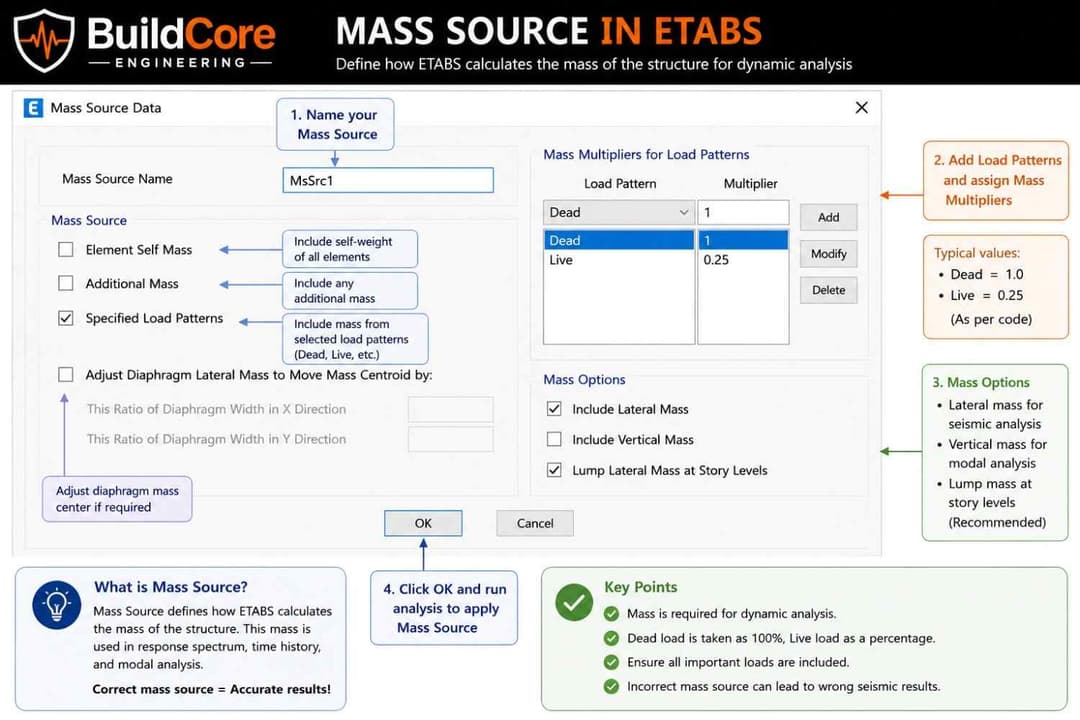
Mistake 1 — Incorrect Mass Source Definition
What goes wrong: Engineers assign loads correctly but forget to define — or incorrectly define — the Mass Source. ETABS defaults to using self-weight only, which dramatically underestimates seismic mass and produces unconservative base shear values.
Why it matters: Seismic force is . An underestimated mass means underestimated forces across every floor, every column, every foundation.
How to fix it:
Navigate to Define → Mass Source and set it to From Loads with the following multipliers:
DEAD    ×  1.00   → All permanent structural weight
SDL     ×  1.00   → Superimposed dead: finishes, MEP, cladding
LIVE    ×  0.25   → Per ASCE 7-22 §12.7.2 (adjust per local code)
Then confirm each Modal and Response Spectrum load case references this Mass Source under Define → Load Cases.
Rule of thumb: After running modal analysis, check
Display → Show Tables → Modal Participating Mass Ratios. Cumulative participation must reach ≥ 90% in each direction per ASCE 7.
Mistake 2 — Wrong Diaphragm Assignment
What goes wrong: Engineers assign rigid diaphragms to every floor by default — including floors with large openings, ramps, setbacks, or irregular plan geometry where a rigid diaphragm assumption is physically invalid.
Why it matters: A rigid diaphragm forces all nodes at a floor level to move together. In irregular floors, this artificially stiffens the structure, redistributes forces incorrectly, and misrepresents how loads travel to lateral resisting elements.
The three diaphragm types in ETABS:
| Type | When to Use |
|---|---|
| Rigid | Regular, solid floor plans with aspect ratio ≤ 3:1 |
| Semi-Rigid | Floors with openings > 50% of area, irregular plans, long narrow bays |
| None | Floors that provide no lateral load distribution (e.g., open parking levels) |
How to fix it:
- For floors with significant openings, use
Semi-Rigiddiaphragm and mesh the slab as shell elements - Check plan irregularity per ASCE 7-22 Table 12.3-1 before defaulting to Rigid
- After assigning, verify load paths with
Display → Show Forces/Stresses → Shells
Red flag: If your response spectrum analysis shows identical drifts at every node on a floor with a large atrium opening, your diaphragm assignment is wrong.
Mistake 3 — Not Defining Seismic Load Patterns Correctly
What goes wrong: Engineers use the auto-seismic feature without verifying the input parameters — site class, importance factor, Ss and S1 values, or response modification coefficient R — leading to incorrect equivalent static forces.
Why it matters: Every parameter in the seismic load pattern feeds directly into base shear. An incorrect R factor of 8 instead of 5, for example, reduces your design forces by 37.5% — a catastrophic under-design.
How to fix it:
Go to Define → Load Patterns → [Seismic Case] → Modify Lateral Load:
Ss        →  From USGS hazard tool for your site coordinates
S1        →  From USGS hazard tool
Site Class →  From geotechnical report (do not assume D)
Ie        →  1.0 / 1.25 / 1.5 per occupancy category
R         →  From ASCE 7-22 Table 12.2-1 (system-specific)
Ω₀        →  Overstrength factor — must match your system
Cd        →  Deflection amplification — must match your system
Always cross-check the ETABS-generated base shear against a hand calculation before proceeding with design.
Mistake 4 — Ignoring P-Delta Effects
What goes wrong: P-Delta effects are left disabled for tall or slender structures where second-order effects are significant — typically structures taller than 4–5 stories or those with high gravity loads relative to their lateral stiffness.
Why it matters: P-Delta amplifies lateral displacements and increases moment demands in columns and walls. Ignoring it leads to non-conservative member design and unconservative drift calculations.
The two levels of P-Delta in ETABS:
| Effect | Description | When Required |
|---|---|---|
| P-Δ (large) | Global effect of gravity loads on displaced structure | All structures with significant height |
| P-δ (small) | Local effect on deformed members between floors | Slender columns, tall story heights |
How to fix it:
Go to Analyze → Set Analysis Options → P-Delta Options:
- Enable Iterative P-Delta for nonlinear sensitivity
- Set the number of iterations (typically 3–5 is sufficient)
- Use load combination:
1.0D + 0.5Las the P-Delta load combination per ASCE 7
Check: Compute the stability coefficient per ASCE 7-22 §12.8.7. If , P-Delta must be considered. If , the structure must be redesigned.
Mistake 5 — Incorrect End Releases on Frame Members
What goes wrong: Beam end releases are either omitted when they should be applied (creating unintended moment connections in simple frames) or over-applied (releasing moments in members that are meant to be fully fixed).
Why it matters:
- Missing releases in simple frames attracts moment to beams and columns that aren't designed for it
- Incorrect releases in moment frames eliminate lateral stiffness, causing unrealistic drift and mechanism formation
How to fix it:
Assign end releases deliberately at Assign → Frame → Releases/Partial Fixity:
Simple beam in gravity frame:    → Release M3 at both ends
Cantilever:                      → Fixed at support, free at tip
Moment frame beam:               → No releases (fully fixed)
Brace in pinned connection:      → Release M2, M3 at both ends
After assigning, run the model and check Display → Show Forces → Frames → Moment M3. A simply supported beam should
show zero end moments. A fixed beam should show peak moments at the supports.
Mistake 6 — Skipping Modal Analysis Verification
What goes wrong: Engineers run response spectrum analysis without first verifying that the modal analysis is producing physically meaningful results — correct number of modes, sufficient mass participation, and reasonable fundamental periods.
Why it matters: Response spectrum analysis is only as reliable as the modal results beneath it. If the fundamental period is implausible or mass participation is below 90%, the spectral forces are wrong regardless of how well everything else is set up.
Verification checklist:
| Check | Target | Where to Verify |
|---|---|---|
| Fundamental period T₁ | Approx. 0.1N seconds (N = number of stories) | Modal results table |
| Cumulative mass participation | ≥ 90% in X and Y | Modal participating mass ratios |
| Mode shapes | Smooth, physically plausible deflected shapes | 3D mode shape display |
| Number of modes | Enough to capture 90% mass | Increase if needed |
How to fix it:
Go to Define → Load Cases → [Modal Case]:
- Set Maximum Number of Modes high enough (start with 3× number of stories)
- Review
Display → Show Tables → Modal Information → Modal Participating Mass Ratios - If T₁ seems too short, check for unintended rigid constraints or missing mass
Mistake 7 — Using Default Section Properties Without Cracked Section Modifiers
What goes wrong: Concrete members are modeled with gross (uncracked) section properties. Under lateral loading, concrete cracks significantly, reducing effective stiffness. Using gross properties overestimates stiffness, underestimates deflections, and miscalculates force distribution between elements.
Why it matters: ACI 318-19 Table 6.6.3.1 requires reduced effective stiffness modifiers for cracked sections. Ignoring these makes your structure appear stiffer than it is — your drifts will be artificially low and your periods will be artificially short.
ACI 318-19 recommended modifiers:
| Member Type | Moment of Inertia Modifier (I_eff / I_g) |
|---|---|
| Columns (compression-controlled) | 0.70 |
| Walls (uncracked) | 0.70 |
| Walls (cracked) | 0.35 |
| Beams | 0.35 |
| Flat plates / flat slabs | 0.25 |
How to fix it:
Select all concrete members and go to Assign → Frame → Property Modifiers (for beams/columns)
or Assign → Shell → Property Modifiers (for walls/slabs). Apply the appropriate I modifier values.
Note: Some engineers use 0.5 for all members as a conservative middle ground. This is acceptable for preliminary design but should be refined for final analysis.
Mistake 8 — Incorrect Story Data and Drift Calculations
What goes wrong: Story levels are defined incorrectly — missing intermediate levels, assigning the wrong master joint, or using story heights that don't match actual floor-to-floor heights — leading to incorrect inter-story drift calculations.
Why it matters: ASCE 7 drift limits () are checked at each story. If your story definitions are wrong, ETABS calculates drift over the wrong height, producing ratios that can either miss code violations or flag false ones.
How to fix it:
Go to Edit → Edit Story Data:
- Verify each story height matches architectural/structural drawings exactly
- Confirm the master joint at each level is located at the center of mass
- For sloped roofs or mezzanines, define intermediate stories — do not lump them
After analysis, check drifts at Display → Show Tables → Story Drifts:
Allowable drift Δₐ (ASCE 7-22 Table 12.12-1):
  Risk Category I/II, all other structures:  0.020 hₛₓ
  Risk Category I/II, masonry cantilever:    0.010 hₛₓ
  Risk Category III:                         0.015 hₛₓ
  Risk Category IV:                          0.010 hₛₓ
Mistake 9 — Applying Loads to the Wrong Object Type
What goes wrong: Area loads are assigned to frame elements instead of shell elements (or vice versa), point loads are placed at incorrect nodes, or loads are applied in the wrong local axis direction.
Why it matters: ETABS silently accepts most incorrect load assignments. The model runs, reactions balance globally, but individual member forces are wrong because load transfer paths are incorrect.
How to fix it:
Before running analysis, always verify loads visually:
Display → Show Loads → [Select Load Pattern]
Check that:
- Floor area loads appear on slab shell elements, not beams
- Wind loads are applied to the correct faces and in the correct global direction
- Self-weight multiplier is set to 1.0 for all load patterns except those where you define weight manually
- Point loads on beams reference the correct local axis (gravity loads use global –Z)
Mistake 10 — Not Checking Reaction and Equilibrium
What goes wrong: Engineers run analysis and jump straight to member design without verifying global equilibrium — that the sum of base reactions equals the applied loads.
Why it matters: If reactions don't balance, something is wrong with the model: missing supports, incorrect boundary conditions, load not being transferred to the lateral system, or numerical instability. Designing from an unbalanced model produces wrong results everywhere.
How to fix it:
After every analysis run, go to Display → Show Tables → Reactions and manually verify:
Sum of vertical reactions  =  Total gravity load (DL + LL × tributary area)
Sum of horizontal reactions =  Applied lateral load (wind or seismic base shear)
Cross-check the base shear from response spectrum analysis against your hand-calculated . A discrepancy greater than 5% warrants investigation before proceeding.
Quick Reference — Mistake Avoidance Checklist
Use this checklist before finalizing any ETABS model for design:
- Mass Source defined as From Loads with correct multipliers
- Modal mass participation ≥ 90% in X and Y directions
- Diaphragm type matches actual floor geometry (not defaulted to Rigid)
- Seismic parameters (Ss, S1, R, Ie) verified against USGS data and geotech report
- P-Delta enabled for structures taller than 4 stories
- Frame end releases match actual connection conditions
- Concrete section modifiers applied per ACI 318-19
- Story heights verified against structural drawings
- Loads applied to correct object types and verified visually
- Base reactions checked against hand calculations
Final Word
ETABS will not tell you when your assumptions are wrong. It will run the analysis, produce colourful diagrams, and generate pages of output — all based on whatever you told it. The responsibility for correct modeling lies entirely with the engineer.
Build the habit of questioning every default setting, verifying every result against first principles, and treating hand calculations not as a redundant step but as the only reliable check you have on a complex computer model.
A correct model is not one that runs without errors. It is one where every assumption has been deliberately made and every result has been independently verified.
Latest Articles
Learn structural engineering concepts and practical insights

Strong Column Weak Beam Explained: The Most Important Rule in Earthquake Design
Learn what Strong Column Weak Beam means, why it is essential in seismic design, and how it prevents building collapse during earthquakes.
What is Mass Source in ETABS? A Simple Explanation for Structural Engineers
Learn what mass source is in ETABS, why it is important in seismic analysis, and how incorrect mass definition can lead to wrong results.

How AI is Changing Structural Engineering (And What Engineers Should Know)
Discover how AI is transforming structural engineering, what it can and cannot do, and what engineers need to understand to stay ahead.